
By FencingWise Editorial Team · Updated 17 September 2026.
Establish the installation references
Use the approved plan and elevation to mark the fence line, corners, gates and changes in level. Distinguish panel overall width from the installed post-centre module.
Identify the finished ground datum and the intended bottom clearance. Mark special bays separately, including shortened panels, transitions and locations beside gate posts.
Before excavation or drilling, complete the site's service-location and work-control procedures. The sequence here concerns panel-system fit; foundation dimensions and structural installation remain governed by the approved design.
Sort components by their installation role
Check the delivered panels, line posts, end posts, corner parts and gate interfaces against the schedule. Confirm that clips, clamps, bolts, inserts and caps belong to the selected system.
Keep special panels labelled by location. A shortened panel intended for the final bay can be mistakenly used early in the run if it looks similar in the pack.
Open one complete connection kit before production installation. Establish the assembly order, tool access and any irreversible fastening step. This avoids discovering a missing spacer after several bays have been tightened.
Build and inspect a representative trial bay
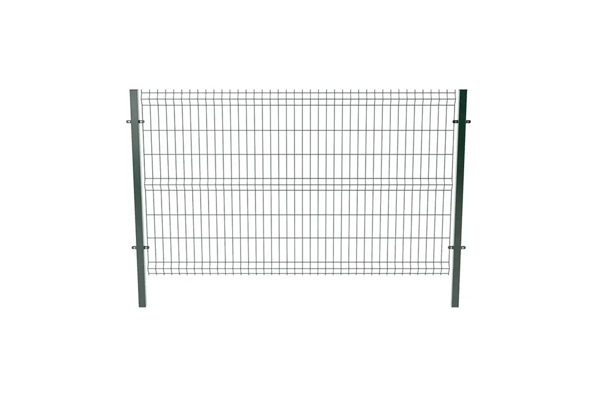
Use the actual panel, two supports and the full connection detail. Check:
- Installed post-centre spacing and orientation.
- Panel engagement at both edges.
- Top elevation and bottom clearance.
- Clip or clamp contact with the intended wires.
- Available adjustment and tool access.
- Coating condition after handling.
- Final fastening method and inspection points.
The trial should represent the real support and ground arrangement as closely as practicable. A loose panel held between two unrestrained posts cannot establish the finished installation condition.
Photograph the accepted connection and record the module used. The installation team then has a specific reference.
Understand how a small spacing error accumulates
Assume an illustrative approved module of 2,500 mm between post centres. If an installer repeatedly sets 2,508 mm, each bay gains 8 mm.
Across 20 bays, the difference becomes:
20 × 8 = 160 mm.
The intended run between first and last post centres is 50,000 mm; the repeated error creates 50,160 mm. A final panel may then appear too short even though the panel dimensions are correct.
Do not assume every connection can absorb the 8 mm difference. Check each bay against its permitted arrangement and use independent survey checkpoints so errors do not accumulate unnoticed.
Progress with measured checkpoints
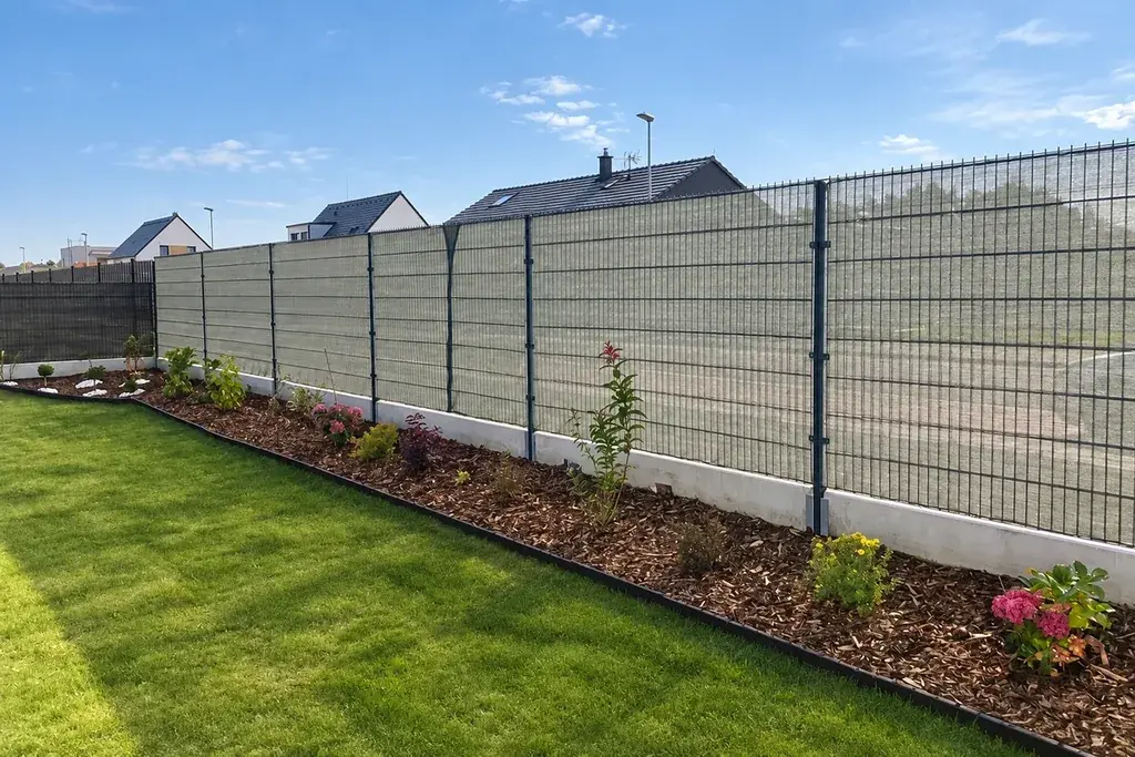
Install supports using the approved method and wait until they are permitted to receive the intended loads. Hold them in the required alignment without relying on the mesh as an improvised brace.
Place panels using suitable handling methods. Protect coated contact areas and avoid dragging panels across the ground.
At defined checkpoints, verify the cumulative position against the original survey references. For example, checking after every 5 illustrative bays would examine nominal stations at 12.5, 25.0, 37.5 and 50.0 m in the 20-bay example. The actual checkpoint frequency belongs to the installation plan, not a universal rule.
Keep corners and gate posts tied to their own set-out references. They should not drift simply because the preceding panels have gradually moved off position.
Resolve the closing bay deliberately
Measure the remaining distance before ordering or cutting a special panel. Record the connection allowance and the finished post positions.
If the remaining geometry differs from the approved schedule, investigate whether the cause is accumulated set-out error, an altered site dimension or a genuine special bay. Cutting a panel immediately can conceal an error that affects the entire run.
Any authorised cutting needs a compatible edge detail and coating repair. Do not leave projecting wire ends or assume a touch-up colour alone restores the original protection.
Use the panel-dimension method when a manufacturing discrepancy is suspected.
Tighten, inspect and record the installed system
Complete fastenings using the system-specific method after alignment has been accepted. Inspect all connection positions, including low parts that landscaping may later conceal.
Walk the bottom edge and check local depressions between posts. Verify transitions, gates and any areas where one type of panel meets another.
The final record should include the accepted trial detail, survey checkpoints, special-bay dimensions, authorised changes and defect closures. Use the handover inspection guide to assemble that evidence.
This sequence makes each repeated bay a controlled installation step. The result is a fence whose fit can be explained from its drawings and measurements, rather than a series of adjustments remembered only by the crew.