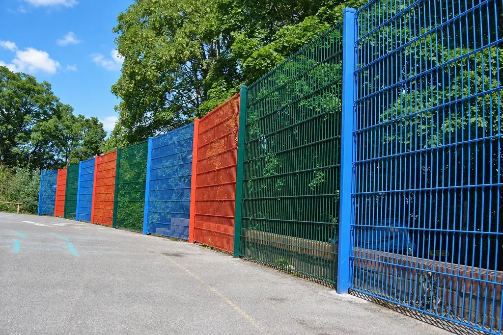
Define the panel before setting the welding fixture
A typical 656 description refers to paired 6 mm horizontal wires with a 5 mm vertical wire between them; 868 uses a different wire combination. Keep the exact construction and measurement convention on the drawing rather than relying on the three-digit name alone.
Specify wire-centre positions, finished panel dimensions, edge projections and any special trimming. If dimensions are quoted before coating, identify the finished requirements separately. The 656 and 868 comparison explains the construction difference; this article focuses on controlling the chosen construction in production.
A first-off panel should be checked against the current drawing before its settings are used for a batch. Retain the material identity and fixture or programme reference so a later discrepancy can be investigated without guessing which version was produced.
Count crossing stations and interfaces correctly
Consider an illustrative grid with 10 vertical wires and 8 horizontal twin-wire levels. It has 10 × 8 = 80 crossing stations. At each station the vertical wire contacts two horizontal wires, giving 160 intended wire-to-wire interfaces in the defined construction.
That count does not specify a welding machine's operating sequence or prove joint strength. A machine may form multiple joints in one operation. The useful distinction is between a visible crossing location, the intended interfaces and the records used to evaluate them.
If an inspection sheet simply says “80 welds checked,” ask which interfaces were examined and by what method. Visual appearance and a destructive strength test answer different questions. Use the drawing and agreed inspection plan to remove that ambiguity.
Check pitch separately from clear opening
Suppose the specified horizontal distance between vertical-wire centres is 50 mm and the relevant vertical-wire diameter is 5 mm. The ideal clear distance between those parallel wires is 45 mm before considering the defined coating and tolerance convention.
Likewise, a 200 mm centre spacing between horizontal levels with 6 mm wires gives an ideal clear distance of 194 mm between the corresponding wire surfaces. These calculations describe geometry, not allowable variation. Measure the actual panel under the agreed method and compare it with the specified limits.
| Feature | Useful measurement | Reason to keep it separate |
|---|---|---|
| Overall size | Finished width and height at defined locations | Does not establish local pitch |
| Wire pitch | Centre distances across several intervals | Reveals grid positioning |
| Clear opening | Surface-to-surface gap under the agreed convention | Relates to the usable aperture |
| Paired-wire alignment | Relative position of the two horizontals | Identifies displaced or missing members |
| Flatness and squareness | Defined reference surface and diagonal method | Affects installation fit |
Inspect the first-off panel before repeating it
- Verify incoming wire identity and the specified diameters.
- Compare fixture positions with the current drawing.
- Measure the grid, outside dimensions and edge treatment on the first panel.
- Inspect paired-wire position and visible joint condition.
- Perform the agreed joint tests on identified samples where required.
- Record approval or correction before releasing the production settings.
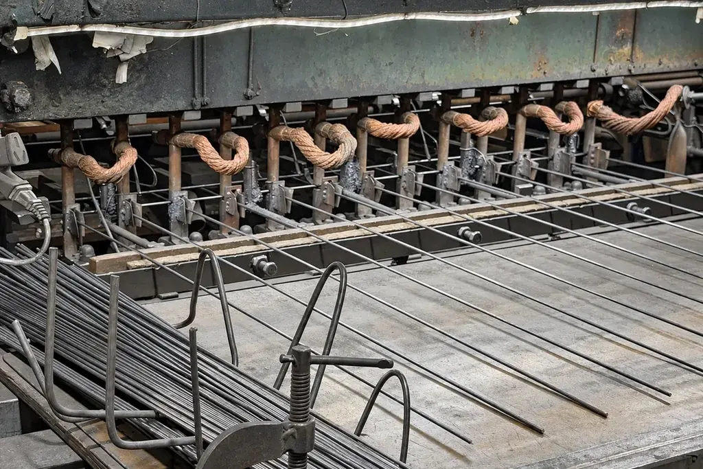
Resistance welding uses heat generated by electrical resistance together with force; TWI describes its process family in its resistance-joining overview. Actual welding parameters belong in a qualified production procedure, not a generic purchasing article.
Do not invent a current, time or force setting from wire diameter alone. Equipment, materials, contact condition and the validated procedure all matter.
Preserve failures and corrective action
If a joint or dimensional check fails, identify the affected material and production interval. Record the correction and the basis for deciding which panels need additional examination. A passing repeat sample should not silently erase the original result.
The inspection plan determines sample numbers, test methods and acceptance criteria. A supplier's historical sampling percentage is not automatically suitable for another order. Avoid treating an average joint result as sufficient where the agreed criterion applies to individual results.
Verify the finished panel after coating and packing
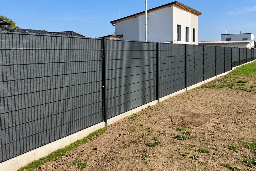
Finishing and handling can affect fit or condition. Check the finished connection areas, identification and any damage before packing. Use the approved panel reference on the bundle labels so receiving staff can link the delivery to the inspection record.
The weld inspection guide develops the evidence review, while dimensional acceptance addresses measurement records. Together they prevent a correct-looking panel from being accepted on appearance alone.