
By FencingWise Editorial Team · Updated 17 September 2026.
It does not replace the site foundation design or, for powered gates, the safety assessment of the completed installation.
Freeze the opening and component references first
The released drawing should identify usable clear opening, leaf arrangement, post positions, movement direction, hardware and coating. Distinguish the required passage from the width of the fabricated leaf.
For a pair of leaves, identify the active and inactive sides and the intended closing sequence. For a sliding gate, show the support arrangement, full travel and open/closed positions. A front elevation without movement information cannot establish whether the finished assembly fits the site.
Keep buyer approval and technical design responsibilities clear. A fabrication approval records the agreed supply configuration; it is not automatically approval of every foundation or automation detail.
Check cut parts and the frame before infill
Compare material sections, wall thickness where specified, cut lengths and joint preparations with the fabrication drawing. Identify hinge, latch and infill fixing positions before they become harder to access.
During frame assembly, measure the defined width and height, both diagonals and the required flatness references. These checks should follow the fabrication procedure and agreed tolerances rather than an improvised “looks square” decision.
For a fictional rectangular frame 2,000 mm wide and 1,800 mm high, the ideal corner-to-corner diagonal is:
√(2,000² + 1,800²) = 2,690.72 mm.
Actual reference points must match the drawing. Measurements to rounded outer corners cannot be compared directly with a calculation between different centreline references.
Interpret the diagonal readings correctly
Suppose a hypothetical inspection records 2,691 mm and 2,695 mm between the specified opposite corners. Their difference is 4 mm.
That difference is an observation, not an automatic pass or fail. The applicable requirement must state how squareness is assessed and what limits apply. Equal diagonals alone also do not prove correct width, height or flatness.
Record the raw values with the instrument and component reference. If corrective work is needed, repeat the affected dimensional checks afterwards. Do not retain only the more favourable final number while losing the original discrepancy.
The panel-tolerance method uses the same principle: measurement, requirement and decision remain separate entries.
Fit the infill and review its edges
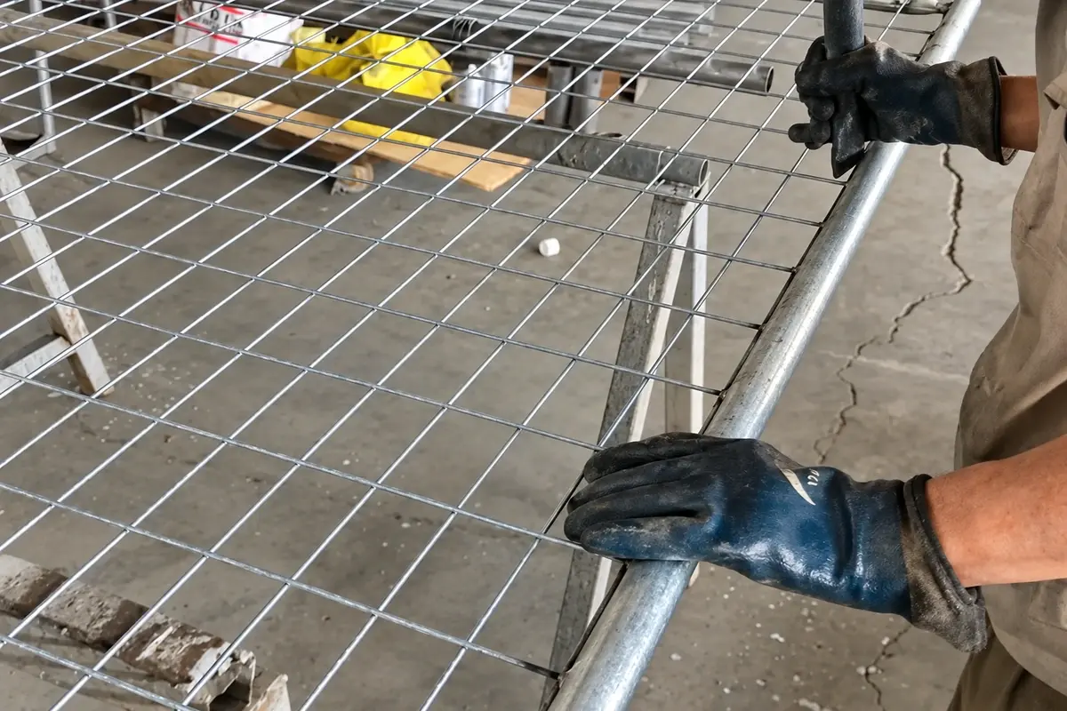
The infill should match the specified mesh, bars or other material and its orientation. Examine the connection to the frame, edge treatment and spaces around the infill.
Adding a visually similar mesh can change mass, fixing geometry or the intended function. If the infill changes, review the leaf, hardware and supporting design rather than assuming the frame makes the substitution irrelevant.
Avoid protruding or unfinished details inconsistent with the approved user-facing surfaces. Record observed defects against the defined acceptance requirements and repair procedure.
Trial the hardware as a connected system
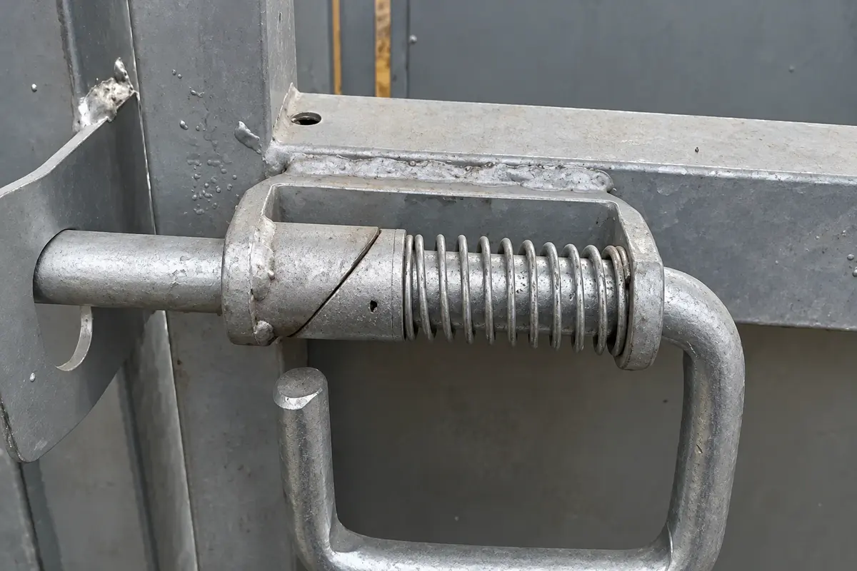
Use the specified hinges or sliding supports, lock or latch, receivers, stops, retention parts and any drop-bolt sockets included in the supply. Record which items were physically present and which were represented by a fixture.
A workshop fixture can establish certain dimensional relationships. It cannot prove the condition or suitability of a future site's foundations. A trial without the actual receiver should not be described as a complete locking-system test.
A useful trial record includes:
| Check | Evidence to retain |
|---|---|
| Hardware identity | Part code and revision |
| Opening and closing movement | Observed travel in the defined fixture |
| Latching or meeting position | Alignment and operation against the drawing |
| Stops and retention | Installed parts and positions checked |
| Removable parts | Identification for reassembly after transport |
| Exceptions | Any site-supplied interface not demonstrated |
Recheck usable passage after hardware is included
Assume an illustrative entrance has 4,000 mm between inner post faces. In the specified fully open position, the leaf and hardware project 25 mm into the passage on the left and 35 mm on the right.
The usable width is:
4,000 − 25 − 35 = 3,940 mm.
If the project requires 4,000 mm usable passage, this hypothetical arrangement does not achieve it. Renaming it a “4 m gate” does not correct the shortfall.
These numbers demonstrate measurement logic, not recommended clearances. The clear-opening guide explains which dimensions belong on the final assembly drawing.
Include finishing and transport in the trial plan
An early bare-metal trial can identify fabrication problems, but coating may affect moving or closely fitting interfaces. Define which checks are repeated after finishing and how any separately packed hardware is identified.
Mark mating parts without damaging the approved finish. If hinges, wheels or receivers are removed for packing, retain an assembly record showing their locations and settings where relevant. Protect projecting parts so transport loads do not bear on them.
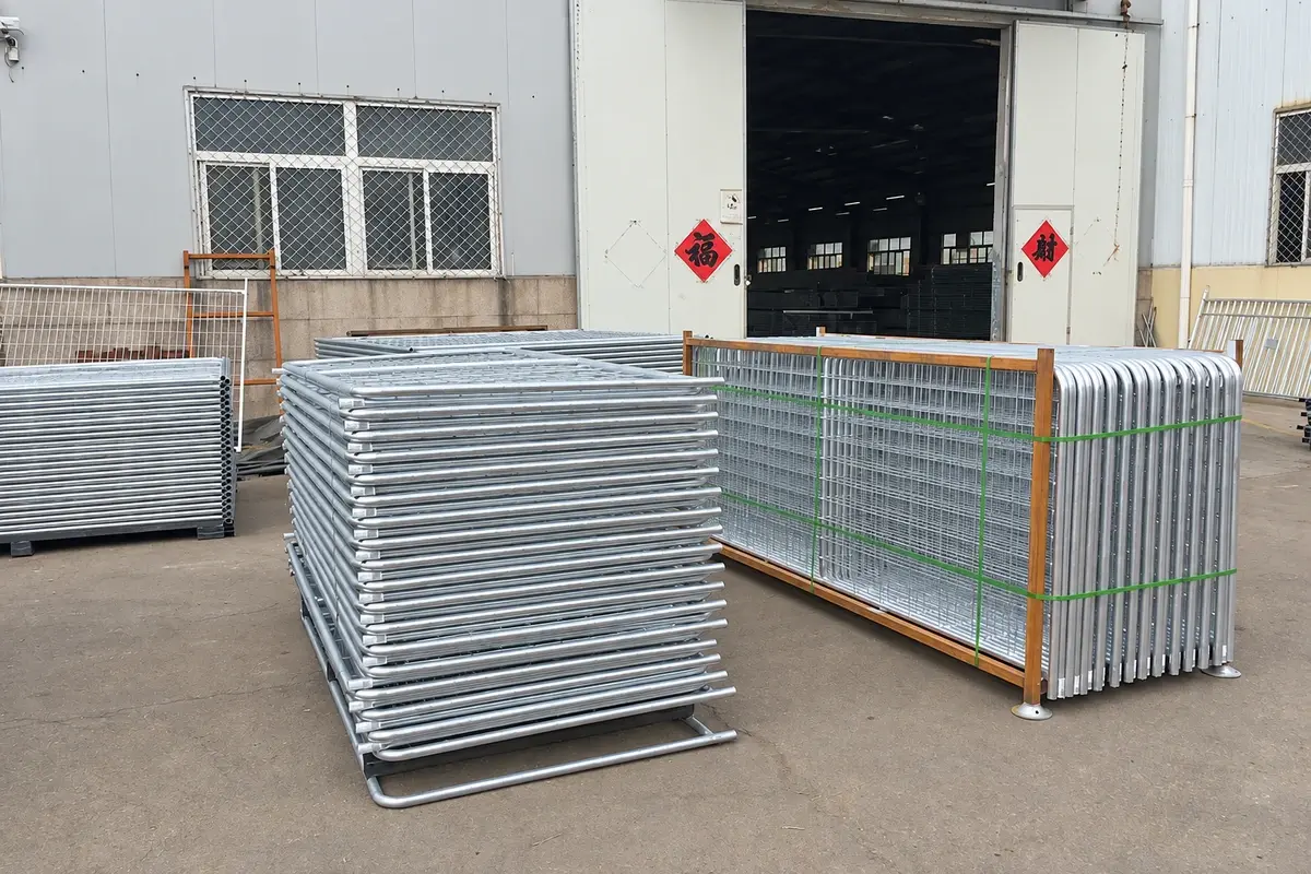
The packing list should distinguish the gate leaf from its hardware and posts. One crate labelled “gate” does not establish that every installation component is inside it.
Know what workshop approval does not establish
A powered gate introduces hazards and safeguards beyond fabrication fit. HSE's powered-gate guidance addresses the need to assess the completed powered installation. A smooth manual workshop movement is not a substitute for that work.
The handover from fabrication should therefore provide a defined assembly, recorded checks and clear remaining site interfaces. Use the gate drawing checklist before release, then keep the trial record with the final revision. This gives the installer evidence they can use rather than a generic statement that the gate was “tested”.