
By FencingWise Editorial Team · Updated 17 September 2026.
For buyers, the most useful production information connects each stage to a measurable feature of the order. A list of machines without those connections says little about the supplied panel.
Release the drawing and material requirements
Before cutting wire, identify panel width and height, wire sizes, opening convention, edge projections, profiles, coating route and the relevant inspection requirements. The production record should point to the same drawing revision as the purchase order.
Material checks establish that the wire corresponds to the required material and dimensions. Record the basis of the diameter: steel, metallic-coated wire or finished polymer-coated wire. Measuring a final outer diameter does not by itself establish the steel core.
If an incoming batch is substituted, assess the effect on the process and product before using it. A familiar supplier name does not replace identification of the material actually received.
Straighten, cut and count the wires
Straightening and cutting prepare the pieces for the panel layout. Required cut lengths depend on overall dimensions and edge detail; formed panels also need the developed length through the bends.
Consider a deliberately simplified flat panel. Suppose vertical-wire centres extend from 0 to 2,000 mm at 50 mm intervals, and horizontal-row centres extend from 0 to 2,000 mm at 200 mm intervals. Both ends contain a wire or row.
The counts are:
Vertical wires = 2,000 ÷ 50 + 1 = 41.
Horizontal rows = 2,000 ÷ 200 + 1 = 11.
The extra one counts the wire at the starting reference. These centre spans are not the outside-to-outside panel dimensions. Wire radii and any edge projections must be included when defining the actual overall size.
The example shows why simply dividing width by pitch can undercount one edge wire.
Position and weld the intersections
In the same hypothetical single-horizontal-wire panel, the layout has:
41 × 11 = 451 crossing positions.
A twin-horizontal arrangement has two horizontal wires at each row. That gives 41 × 11 × 2 = 902 wire-to-wire contact positions in this simplified geometry.
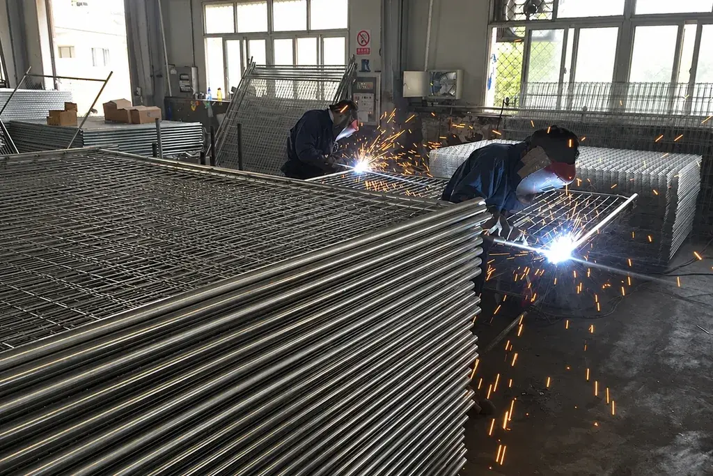
Those counts are not a statement about machine cycles, electrode arrangement or production rate. A welding machine may make several joints within its configured operation. Do not infer output per minute from the number of intersections on the finished panel.
Resistance welding depends on controlled process conditions appropriate to the materials and joint. TWI's guidance on consistent resistance spot welds emphasises settings, process control and verification. It discusses welding principles; it does not provide a universal fence-wire recipe.
Inspect before forming and finishing
A useful intermediate inspection can catch incorrect wire positions, missing joints or dimensional errors while they remain visible and accessible. The specified method should distinguish visual observations from tests of joint performance.
A panel that looks regular does not automatically have adequate weld strength. Where tests are required, identify the sample, test method, loading arrangement, acceptance criterion and represented batch. The weld inspection guide explains how to read those records.
Do not use a machine-setting printout as the only evidence that every joint meets the product requirement. Settings describe the process; verification examines its result.
Form the profile where the design requires it
For a profiled panel, inspect bend count, depth, location and direction. Forming changes the wire path and the panel's projected geometry, so the production drawing must distinguish developed and finished dimensions.
The V-bend article calculates the extra wire in a simplified profile. At the production stage, the actual tooling radius and forming method must be considered.
Check the formed panel with the intended connection. A correct overall height does not help if a bend lies where a clip must seat. Record any forming-related damage or deviation and use the approved disposition process.
Apply the specified coating route
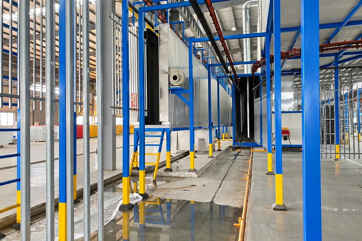
The sequence may use pre-coated wire with defined treatment after fabrication, or galvanizing after fabrication followed by any specified additional finish. Record which route applies instead of writing one generic “galvanized” entry.
Inspect the required surfaces and locations at the relevant stage. Once powder coating covers the panel, a visual check cannot reconstruct the underlying zinc treatment. The combined-coating specification guide shows how to separate layer evidence.
Preparation, application and curing requirements belong to the actual coating system. No single oven time or temperature should be copied across different powder products and component arrangements.
Verify the finished panel and its matching parts
After finishing, check overall dimensions, wire/mesh references where accessible, profile geometry, edges and visible condition against the order. Trial fit the finished panel with its post and fixing arrangement where that is part of the inspection scope.
A small coating build-up or changed fitting can affect the finished joint even when the bare parts fitted earlier. Retain the actual component references used in the trial.
Then reconcile accepted quantities with packing. Separate damaged or held items from released goods; a production total is not necessarily a dispatch quantity.
Ask for records that follow the product
A practical manufacturing record links material identification, drawing revision, relevant process checks, dimensional results, specified weld evidence, coating records and final quantities. It should remain possible to identify which shipment those records cover.
FencingWise combines in-house production and partner sourcing. This article explains a manufacturing route and its purchasing checks; it does not claim that every product uses one machine line or that every test is included in every order. The factory and supply page identifies the company role, while the order defines the actual inspection and document scope.